module demo1(
    input B, D, // Declare inputs
    output A, C // Declare outputs
);

    // Content of module
    assign C = ~A;
    assign A = ~B & D;

endmoduleDeeper Dive on Verilog Syntax
Basics of Verilog Operations
Basics of Verilog Modules
The Top File
Vivado Tips on Top
Make sure that the top file is bolded and marked with the three blocks

Ensure to read the "How To Verilog"
Included in this lab is a document on how to read verilog

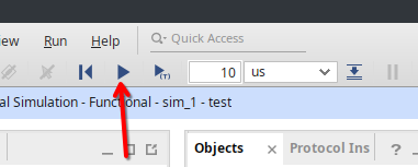
Frequently run Simulation
Ensure to hit "Run All" to finish sim