Introduction
In this week’s lab, we will investigate more advanced combinatorial logic equations and circuits. Now that you have the beginnings of understanding when it comes to Verilog, we can help you learn more in depth on the usage of verilog and digital logic.
We will be building a few more complicated circuits and discuss more about the physical structures of modern logic circuits, as well as real-life applications.
Stairway Lights
To start, let’s look at a contrived example. Imagine we want a to control a light switch from two different places – like on a stairway, where one switch is at the top of the stairs and the other at the bottom. Initially, we may want to hook things up like this:
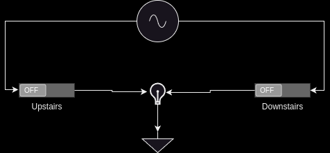
Say you wanted to go upstairs to bed. You would turn on the downstairs switch, and begin walking up the stairs. This will connect the power source through the switch and turns the bulb on:
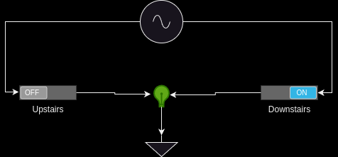
You walk upstairs and flip the upstairs switch. This connects the power source through the switch and… well. Shoot. You can’t turn the light off! No matter what you do, no matter what state the upstairs switch is in, the light remains on. The state table for our light looks rather a lot like that of the OR gate:
| Down | Up | Stair Light |
|---|---|---|
0 |
0 |
0 |
0 |
1 |
1 |
1 |
0 |
1 |
1 |
1 |
1 |
Where if either switch is on, regardless of the other, the light is on. Obviously, this is not the behavior we want. Rather, we want this style of behavior:
| Down | Up | Stair Light |
|---|---|---|
0 |
0 |
0 |
0 |
1 |
1 |
1 |
0 |
1 |
1 |
1 |
0 |
Where if only one of the two switches is on, but not both the light will be lit. In a house, we would wire this up like this:
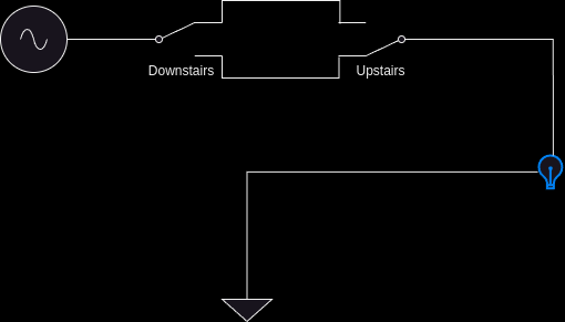
Now, as we can see, if we were to flip the downstairs switch, there would be a path from the power through the switches, through the light, then to ground. And, when we get upstairs and flip that switch, the circuit is interrupted and the light goes out. You may notice, by comparing to previous week’s lab, that this is the XOR truth table. This is a real example of how various logic equations can be used in the real world to solve actual problems.
TASK: The file light.v includes the skeleton of a Verilog module for
you to implement. Go ahead and declare two inputs: downstairs and
upstairs as well as one output stair_light. Then, using the syntax
learned in the previous lab, implement this XOR light switch equation.
Set this up in your top level file with the following input/output
table:
| Pin | Purpose | Direction |
|---|---|---|
sw[0] |
Downstairs light switch |
IN |
sw[1] |
Upstairs light switch |
IN |
led[0] |
Stairway light |
OUT |
Let’s go bigger
Cool… so we can turn a stairway lightbulb on and off
You, probably.
Yes, actually, that is super cool. In fact, it is foundational cool, and I will show you how throughout the rest of this lab.
What if I told you that this light switch system is actually doing math? I know it sounds like a stretch, but let’s walk through this. You ever heard the joke "There are 10 kinds of people in this world, those who understand binary and those who don’t"? We’re going to get you into that first category here.
The way we normally do math is in a system called Base Ten. That means there are ten different numbers in each digit. In our case, we represent them with the numbers 0 through 9. Since there are ten values in each digit, each place contains 10x the value of the previous, we call these the one’s place, ten’s place, hundred’s place, and so on:
1234
^^^^
|||└-: One's place
||└--: Ten's place
|└---: Hundred's place
└----: Thousand's place
That is to say: the decimal number 20 is 10 larger than 10. Even though we changed that number by a 1, it was in the tens place, so it got 1 * 10 bigger. Each number in a place is multiplied by its digit. So a 1 in the Thousand’s place is actually worth 1000, not 1. This may seem like a whole lot of words to explain the readily obvious. But it is important we get down to the foundation of how a number represents its values in its digits, because we’re about to switch bases. Computers think in binary, or Base Two. That means each digit can only contain two values: 0 and 1. That means we don’t have the One’s, Ten’s, Hundred’s, etc digit, we have the One’s, Two’s, Four’s, Eight’s, Sixteen’s, etc. Because each digit is 2x as large as the last, as opposed to 10x with Base Ten.
0101
^^^^
|||└-: One's place
||└--: Two's place
|└---: Fours's place
└----: Eight's place
So just as we can get the value of 1234 as
(4 * 1) + (3 * 10) + (2 * 100) + (1 * 1000), we can ge the value of
0101 as (1 * 1) + (0 * 2) + (1 * 4) + (0 * 8), or 5. Of course, 1234
is already decimal so it is fairly trivial for us to understand the
value because we’re used to thinking in it, but it still proves the
point.
What on earth does this have to do with our light switch, though? Let’s
consider a single digit binary number. As we’ve described above, given
it is Base Two, it can have two states: 0 or 1. Well… our light can
either be off or on, so that maps pretty well. We can represent the
state of our stair light with a single binary digit. What is 0 + 1 in
binary? Thankfully this is exactly as straightforward as it looks: 1.
However, what happens if we do 1 + 1 – well, now we get to the
punchline of our joke, because that’s 10. Just like when you add
9 + 1 = 10 in decimal, we move to the next digit, since we are past
the end of our base. 9 + 1 is actually 0, carry the 1. That means,
if we only have a single binary digit, 1 + 1 = 0, since we can’t carry
the 1 to the next digit. Let’s look at the results of a single digit
binary summation in a table, where we are doing A + B = Y:
| A | B | Y |
|---|---|---|
0 |
0 |
0 |
0 |
1 |
1 |
1 |
0 |
1 |
1 |
1 |
0 |
You may notice something: that’s the output table for our properly wired switch from above. So, long winded explanation aside, the XOR switch pattern for our stair light is doing binary addition of a single digit. It is doing math.
Basic Adder
Some of you have likely noticed at this point that the lab is titled
Combinatorial Logic, yet we have only combined one logic gate here
today. I promised some more advanced combinatorial logic equations and
circuits, and you’re right to demand them! Let’s add one more thing
into our… adder. Just how when doing addition in Base Ten we carry out
to the next digit where 9 + 1 = 0 + carry the 1, we do the same in
binary. Let’s look at the full truth table for an adder A + B = Y:
| A | B | Y | Carry |
|---|---|---|---|
0 |
0 |
0 |
0 |
0 |
1 |
1 |
0 |
1 |
0 |
1 |
0 |
1 |
1 |
0 |
1 |
If we isolate just the carry bit, the table looks like this:
| A | B | Carry |
|---|---|---|
0 |
0 |
0 |
0 |
1 |
0 |
1 |
0 |
0 |
1 |
1 |
1 |
Which, if you look at last week’s lab, is the AND gate. That means we can have a single digit binary adder that looks like this:
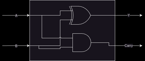
Where the logic equations are:
Y = A ^ B;
Carry = A & B;
TASK: You probably know what’s coming now. There’s an adder.v file
with a stubbed out module for you to implement. Fill out the required
equations and complete the implementation of the single bit adder. Wire
this up in your top level module according to the following I/O table:
| Pin | Purpose | Direction |
|---|---|---|
sw[2] |
A for one bit adder |
IN |
sw[3] |
B for one bit adder |
IN |
led[1] |
Y (sum output) of one bit adder |
OUT |
led[2] |
Carry out of one bit adder |
OUT |
2-bit Adder
This lab is all about combinatorial logic, so let’s slam two of these together to add two bit numbers together instead. We will call these four bits (two bits per number, two numbers) A, B, C, D:
B A + D C
I have assigned them in least to most significant digit to make the following diagrams easier to read.
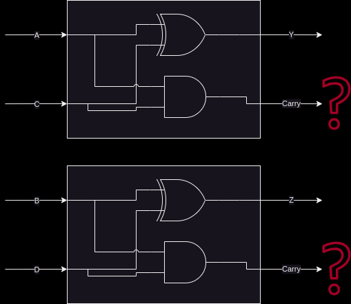
Well… what on earth do we do with the carry signals? There’s nowhere to
put them, the second adder summing B + D cannot take into account the
carry from the previous bit. If we look at the what this means, let’s
add the numbers 11 + 01:
B A     D C
1 1  +  0 1

A + C = 0, carry 1
B + D = 1, carry 0

11 + 01 = 10
Sadly for our nice little two bit adder, this answer is completely wrong. Thankfully, we can return back to our decimal addition from elementary school for inspiration:
Step 1:
     v
C
    12
+   19
------

9 + 2 = 11, or 1, carry the 10

Step 2:
    v
C   1
    1
+   11
------
1 + 1 + 1 = 3

= 31
Step 2 above has our secret. Notice how we combine the carry-out from the previous number (9 + 2) over on top of our second number (1 + 1). Therefore, to get the second digit in our base ten sum above, we actually needed to add three different numbers together, the ten’s place from 12 and 19, as well as the carry from the 9 + 2.
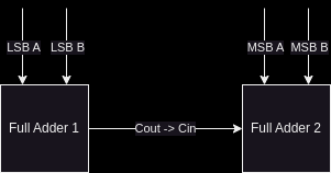
All we have to do is do the same thing to our 1-bit adder – instead of summing just one bit from each number, we also need to include the carry-in from the previous digit. In other words, we need to sum three bits together, aka a full adder.
TASK (Full Adder ): The truth table for this is below. Implement it in the file
full_adder.v. Cin means carry-in, and Cout means carry-out. You can
think of this as two three-input equations, one where Y is composed of
A, B, and Cin and the other where Cout is composed of the same.
You can use KMaps to find these equations.
| A | B | Cin | Y | Cout |
|---|---|---|---|---|
0 |
0 |
0 |
0 |
0 |
0 |
0 |
1 |
1 |
0 |
0 |
1 |
0 |
1 |
0 |
0 |
1 |
1 |
0 |
1 |
1 |
0 |
0 |
1 |
0 |
1 |
0 |
1 |
0 |
1 |
1 |
1 |
0 |
0 |
1 |
1 |
1 |
1 |
1 |
1 |
Then, wire it up in your top level module according to the following I/O table. You will need two instances of a 1 bit full-adder to add two bit numbers together:
| Pin | Purpose | Direction |
|---|---|---|
sw[4] |
LSB of A for two bit adder |
IN |
sw[5] |
MSB of A for two bit adder |
IN |
sw[6] |
LSB of B for two bit adder |
IN |
sw[7] |
MSB of B for two bit adder |
IN |
led[3] |
LSB of two bit sum |
OUT |
led[4] |
MSB of two bit sum |
OUT |
led[5] |
Carry out of MSB adder |
OUT |
Lab Deliverables
Summary of IO Table
| Pin | Purpose | Direction |
|---|---|---|
sw[0] |
Downstairs light switch |
IN |
sw[1] |
Upstairs light switch |
IN |
sw[2] |
A for one bit adder |
IN |
sw[3] |
B for one bit adder |
IN |
sw[4] |
LSB of A for two bit adder |
IN |
sw[5] |
MSB of A for two bit adder |
IN |
sw[6] |
LSB of B for two bit adder |
IN |
sw[7] |
MSB of B for two bit adder |
IN |
led[0] |
Stairway light |
OUT |
led[1] |
Y (sum output) of one bit adder |
OUT |
led[2] |
Carry out of one bit adder |
OUT |
led[3] |
LSB of two bit sum |
OUT |
led[4] |
MSB of two bit sum |
OUT |
led[5] |
Carry out of MSB adder |
OUT |
Required modules to implement
-
Implemented light switch module in
light.vdescribed in this section -
Implemented single bit adder in
adder.vdescribed in this section -
Implemented full adder in
full_adder.vdescribed in this section -
In
top.v, combine the three blocks below as per IO table provided in this section- Light Switch Module
- Basic Adder
- 2-bit Adder (Note: Use full adders to build 2-bit adder as described in this section)
-
Update
constraints.xdcas per IO table description -
Demonstrate the combined design to TA or lab professor