Making The Circuits Remember

Continuous Assignment

  • Continuous assignment always happens

  • Cannot "wait" for an event

  • Cannot "remember" the past

Diagram

Synchronous Logic

  • Happens on certain events

  • Signals the output is synchronous to

  • Contains memory

Diagram

The SR-Latch

  • Basic form of memory

  • Uses combinatorial loops

  • Should be implemented using behavioral verilog

  • Careful of invalid state!

sr latch.drawio

Truth Table and Considerations

Table 1. SR-Latch Truth Table

S

R

Q

~Q

0

0

Latch

Latch

0

1

0

1

1

0

1

0

1

1

0

0

Structural Implementation

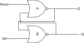
module structural_sr_latch(
    input Set,
    input Reset,
    output Q,
    output NotQ
);

    assign Q = ~(Reset | NotQ);
    assign NotQ = ~(Set | Q);

endmodule

Behavioral Implementation
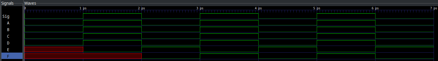
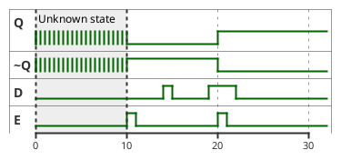
module behavioral_sr_latch(
    input Set,
    input Reset,
    output reg Q,
    output NotQ
);

    always @(Set, Reset) begin (2)
        if (Set)
            Q <= 1; (3)
        else if (Reset)
            Q <= 0;
    end

    assign NotQ = ~Q; (1)

endmodule
1Note the use of continuous assignment here
2Synchronous only to Set and Reset
3Non-blocking assignment

The D-Latch

Table 2. D-Latch Truth Table

Enable (E)

Data (D)

Q

~Q

0

0

Latch

Latch

0

1

Latch

Latch

1

0

0

1

1

1

1

0

Diagram

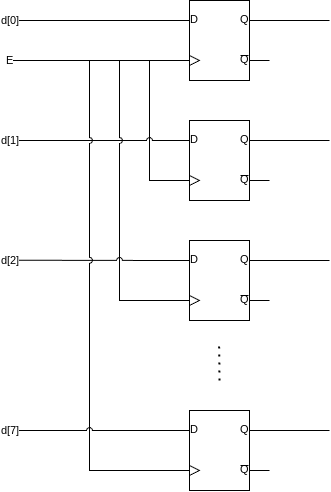
Making Higher Order Memory

  • Enable lines tied together

  • One D-Latch per bit

  • Outputs as a vector

eight bit mem.drawio

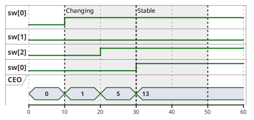
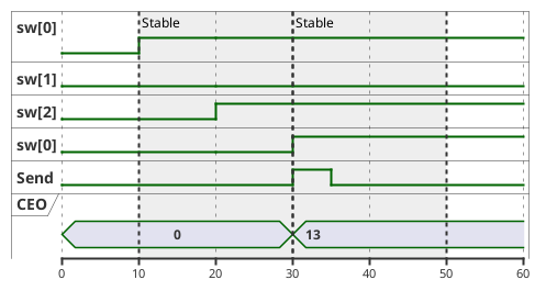
Making Computer Memory

  • More than one value!

  • Address line selects which to read/write

  • Can change switches and only save when button pressed
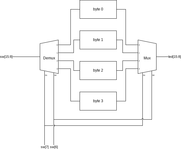
block diagram.drawio

How it Should Work

New Syntax

  • Array Syntax

  • Demultiplexer

  • Loop, genvar, and parameter

Array Syntax

1Vector: 8 bits
2Array, four 1 bit signals
3Array of vectors, four 8 bit signals
module arrays();

    // Traditional vector:
    wire [7:0] vect; (1)

    // Array:
    wire arr[3:0]; (2)

    // Array of vectors:
    wire [7:0] arr_vec[3:0]; (3)


endmodule

Array Syntax, Pt. 2

1Grab one 1 bit signal
2Grab one 8 bit signal
3Grab one 8 bit signal, then the 8th bit
    // Single signal:
    assign arr[2] = 'b1; (1)

    // Single signal:
    assign arr_vec[3] = 8'b10100101; (2)

    // Single bit of single signal:
    assign arr_vec[2][7] = 1; (3)

Demultiplexer

1We change on data or sel
2Concat into structured assignment, other outs need to be 0
module demultiplexer(
    input [3:0] data,
    input [1:0] sel,
    output reg [3:0] A,
    output reg [3:0] B,
    output reg [3:0] C,
    output reg [3:0] D
);

    always @(*) begin (1)
        case(sel)
            2'b00: {D, C, B, A} <= {4'b0, 4'b0, 4'b0, data}; (2)
            2'b01: {D, C, B, A} <= {4'b0, 4'b0, data, 4'b0};
            2'b10: {D, C, B, A} <= {4'b0, data, 4'b0, 4'b0};
            2'b11: {D, C, B, A} <= {data, 4'b0, 4'b0, 4'b0};
        endcase
    end

endmodule

Loop, genvar, and parameter

1Declare genvar
2generate block
3For loop! no ++
4Regular declaration
5Genvar can be used in assignment
6Parameter in instance list
module sample(
    input X, output Y
);
    assign Y = ~X;
endmodule

module genvar_example
#(
    parameter BIT_COUNT = 16 (6)
)
(
    input [BIT_COUNT - 1:0] sw,
    output [BIT_COUNT - 1:0] led
);

    genvar i; (1)
    generate (2)
        for (i = 0; i < BIT_COUNT; i = i + 1) begin (3)
            sample inst( (4)
                .X(sw[i]), (5)
                .Y(led[i])
            );
        end
    endgenerate
endmodule

Instantiating Parameters

1Passed in before module name
module test();
    reg [15:0] sw;
    wire [15:0] led;

    genvar_example #(.BIT_COUNT(16)) uut( (1)
        .sw(sw),
        .led(led)
    );

    initial begin
        $dumpvars(0,test);
        sw = 0;
        #10;
        sw = 'hFFFF;
        #10;
    end
endmodule

Blocking vs. Non-blocking

module block_nonblock(
    input Sig,
    output reg A, B, C, D, E, F
);

    // Blocking assignment
    always @(Sig) begin
        A = Sig; // A immediately gets sig
        B = A; // B immediately gets sig
        C = B; // C immediately gets sig
    end
    // In blocking assignment, Verilog will generate
    // circuits that require full propogation of signals
    // until continuing

    // Non-Blocking assignment
    always @(Sig) begin
        D <= Sig; // D immediately gets sig
        E <= D; // E gets D next time
        F <= E; // F gets E next time
    end
    // In non-blocking assignment, Verilog will generate
    // synchronous logic that ends immediately, and does
    // not block until all circuits propogate
    // USE THIS UNLESS YOU KNOW WHAT YOU ARE DOING

endmodule

Blocking vs. Non-blocking Output

blocking nonblocking output