Minimizing and Optimizing Logic Equations
Please read more about KMaps for a deeper explanation of KMaps before you proceed.
Take the following truth table, with four inputs and one output:
| # | A | B | C | D | Y |
|---|---|---|---|---|---|
0 |
0 |
0 |
0 |
0 |
0 |
1 |
0 |
0 |
0 |
1 |
1 |
2 |
0 |
0 |
1 |
0 |
1 |
3 |
0 |
0 |
1 |
1 |
1 |
4 |
0 |
1 |
0 |
0 |
1 |
5 |
0 |
1 |
0 |
1 |
0 |
6 |
0 |
1 |
1 |
0 |
1 |
7 |
0 |
1 |
1 |
1 |
0 |
8 |
1 |
0 |
0 |
0 |
0 |
9 |
1 |
0 |
0 |
1 |
0 |
10 |
1 |
0 |
1 |
0 |
1 |
11 |
1 |
0 |
1 |
1 |
0 |
12 |
1 |
1 |
0 |
0 |
1 |
13 |
1 |
1 |
0 |
1 |
0 |
14 |
1 |
1 |
1 |
0 |
1 |
15 |
1 |
1 |
1 |
1 |
0 |
Step 1
Implement a naive equation to describe the truth table above. Simply
encode each line with a 1 as an equation AND-ing together the states
of A,B,C,D in that line, then OR each equation together. You should get
something like this (values entirely for example):
Y = (~A & ~B & ~C & ~D) |
    (~A & ~B & ~C & D) |
    (A & ~B & ~C & ~D) |
    ...
    (A & ~B & ~C & D) |
    (A & B & C & ~D)
Put this into the file naive.v.
Step 2
Turn the truth table into a KMap, then using the minterms encode a SOP
equation. Then using maxterms encode a POS. Implement both in the
minterm.v and maxterm.v files.
Step 3
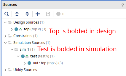
Assemble into top.v, using sw[3:0] as A, B, C, D respectively, and
then led[2:0] as the outputs for each naive.v, minterm.v, and
maxterm.v.
| Signal | Direction | Use |
|---|---|---|
sw[0] |
IN |
D |
sw[1] |
IN |
C |
sw[2] |
IN |
B |
sw[3] |
IN |
A |
led[0] |
OUT |
naive output |
led[1] |
OUT |
minterm output |
led[2] |
OUT |
maxterm output |
Simulate the design (making sure test.v is a simulation only source):
… and make sure the waveforms for led[0], led[1], and led[2] all
match: 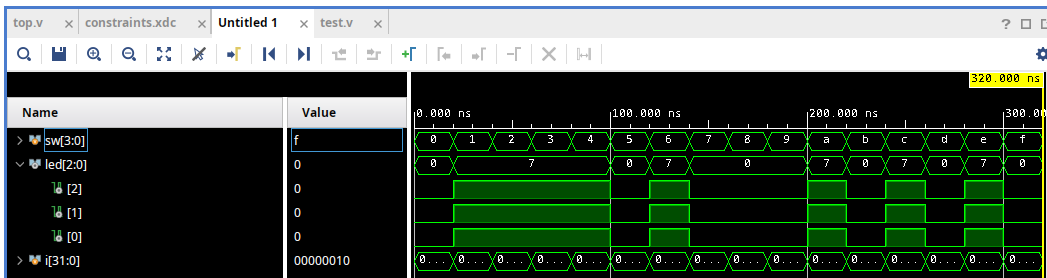
This simulation step allows us to verify that our design is right VERY quickly compared to loading it on device over and over to fix issues. We can see in the screenshot above that the three waveforms for the LEDs match exactly. If we think about the task we’ve been given, we are driving what should be exactly the same equations onto the three LEDs, just two of them are optimized. That means if any of the waveforms are wrong, we’ve not optimized our equation but instead broken it.
If they do all match, generate your bitstream and load it onto your board and demonstrate to your lab professor/TA.
Analysis
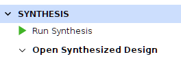
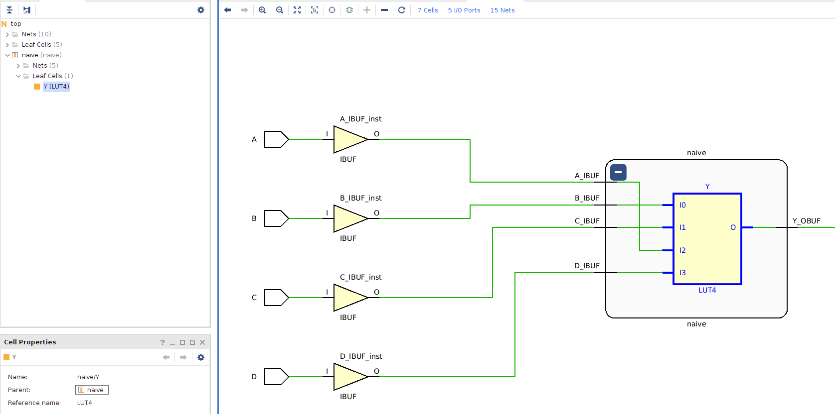
Open the synthesized design in Vivado by clicking Open Synthesized Design:
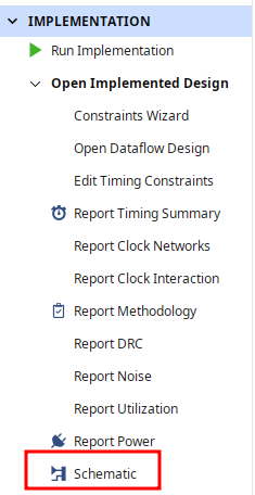
Then, navigate to the schematic, and find the implemented LUT for your naive design:
Expand the naive cell by hitting the + button to expose the LUT,
then select it:
Then, in the Cell Properties window, select the Truth Table tab (you may have to scroll with the small buttons at the bottom of the tabs):
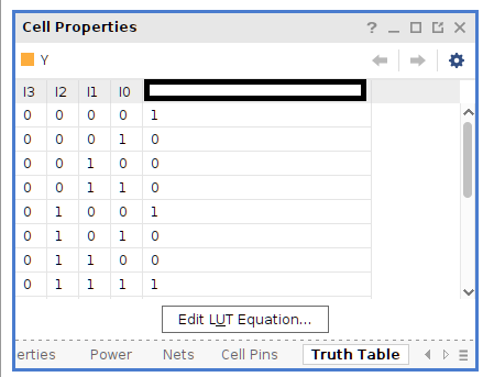
Check out how the LUT equation on the O column exactly matches the SOP
equation we found! Note that the order of A,B,C,D might change so make
sure to take that into account, but it’s the exact same equation. Vivado
and its synthesis tools automatically did all of the optimization for
us. This will generally be the case for all verilog toolchains, and you
will very rarely have to consider the optimization of circuits on your
own.
Further reading
If you are having trouble with the above tasks, refer here for more information about KMaps and SOP/POS.
Lab Deliverables
-
Implement
naive.vwith the maximized version of the truth table above. -
Implement
minterm.vwith the SOP version of the truth table above. -
Implement
maxterm.vwith the POS version of the truth table above. -
Demonstrate the three working logic equations to the lab TA/instructor.